

High Pressure Switching Valve
Quick Start Guide
Manufactured by Newcrom Co. division of SIELC Technologies, Inc.
Unpack your High Pressure Switching Valve and confirm you have all the parts. These include:
- Valve
- USB A-B cable
- HPLC fittings (6)
- Syringe HPLC adapter (2)
- Syringe
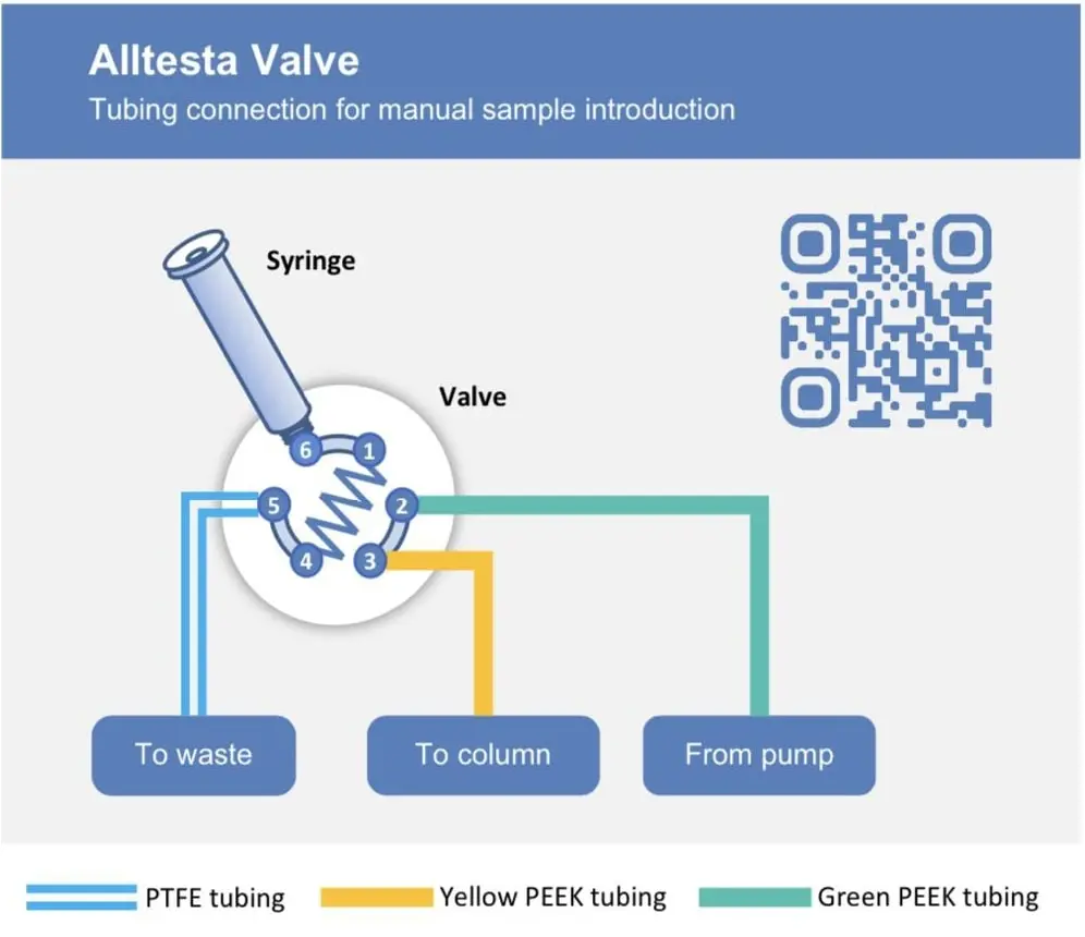
- PTFE Tubing
- Green capillary tubing (low pressure)
- Yellow capillary tubing (high pressure)


Instrument Control
- If you’re using an Alltesta, plug the A-side of the USB cable into the Power Tower.
- The system will recognize the valve automatically and be ready to control at HPLC.cloud within a couple minutes.
- If you’re using an external instrument, plug the other side of the 3.5 mm aux cable into the instrument.
- The rotor will alternate positions every time it receives a signal via the aux cable.
Manual Control
- Click the LED button to alternate the rotor position (from Position 2 to Position 1, etc.).
Computer Control
- Connect the A-side of the USB cable into your computer.
- Open a serial command browser.
- Open the serial command browser.
- The rotor position will be controlled by the variable B1.
- There are 2 possible values (B1 = 1 and B1 = 2), which correspond to each position.
- The initial value B1 = 2, which corresponds to Position 2.
- Before you switch the rotor to Position 1, manually inject your sample so that the loop connecting Port 1and Port 4 is filled completely with your sample.
- Turn on your pump.
- Set B1 = 1 to change to Position 1 to connect Port 1 to Port 2, etc.
- When the valve switches to the pump will inject the sample in the loop into the column.
- You can also write a program using the serial commands to control the amount of time the valve is in Position 1 before it switches back to Position 2.
Instead of drawing a sample with the syringe, and then connecting the syringe to the instrument, which can introduce possible contamination (especially over repeated injections), you can also fill a 1.5 mL vial with sample solution and insert the capillary from Position 5 into the vial. Place an empty syringe with the plunger depressed completely in Position 6. Then pull the plunger to draw solution through the PTFE capillary and into the 1-4 loop. Once you see liquid enter the syringe, stop drawing. After each injection, draw more solution into the syringe to conduct further injections.
Notes
- Green slow blink: Valve is in Standby Mode (Rotor in Position 2);
- Yellow Slow Blink: Booting up software, instrument is getting ready;
- Magenta Slow Blink: Valve is in Injection Mode (Rotor Position 1);
- Cyan Fast Blink: Software updating;
- Red Fast Blink: Hardware/Software Error.
Washing the Valve and Loop
- Fill three 1.5 mL vials with distilled water and label them #1-3.
- Replace the sample vial with Wash Vial #1 on position 5.
- Insert the clear tubing from position 5 into Wash Vial #1.
- Raise the plunger to the max position and then depress the plunger to the minimum position to rinse the valve and loop.
- Replace Wash Vial #1 with Wash Vial #2 on position 5. Repeat Step 4.
- Replace Wash Vial #2 with Wash Vial #3 on position 5. Repeat Step 4.
- Replace Wash Vial #3 with the Waste beaker and remove any remaining water in the valve and loop.
- Remove the Waste beaker and replace it with your next sample.
- This can all be done during sample runs, but only after the injection itself (after the valve exits Injection Mode).
- You can reuse the same wash vials for a few experiments, but make sure to replace the water occasionally in order to minimize the presence of unwanted contaminants.