

Alltesta™ Mini Analyzer with Gradient
Instruction Manual
Manufactured by Newcrom Co. division of SIELC Technologies, Inc.
Introduction
The Alltesta™ Mini Analyzer is a powerful instrument that utilizes high performance liquid chromatography (HPLC), the most popular analytical technique in the world. It is designed to perform multiple liquid chromatographic analytical experiments of a diverse nature. Even though it is smaller and simpler than standard HPLC instruments from other manufacturers, it provides more than enough capabilities to conduct various analyses of numerous real-life samples.
The instrument is controlled by web-based software that requires an Ethernet connection to perform analytical experiments. It incorporates multiple units that include:
- Syringe Pump
- UV/VIS Multi-Wavelength Detector
- Switching Valve
- Electronic module (Power Tower)
- Stand-Alone Syringe Pump (Gradient)
The Power Tower houses a power unit and a communication unit (StreamLC). All modules on the Mini Analyzer, as well as the stand-alone pump, are electrically interconnected via power and USB cables to the Power Tower. The Power Tower is powered via an AC power outlet (110-240V) and connected to the Internet using a CAT5 ethernet cable and is a part of the local computer network.
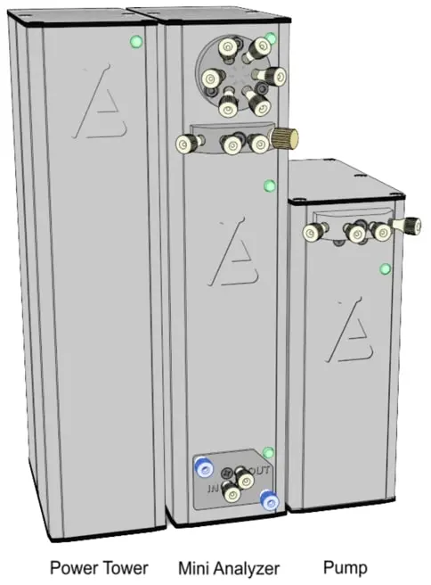
Building your Alltesta™ Mini Analyzer
- Now that you have received the components to your Alltesta™ Mini Analyzer with Gradient system, it’s time to put it all together.
- Place the Alltesta Power Tower on a flat surface.
- Place the Mini Analyzer on a flat surface next to the Power Tower.
- Place the stand-alone pump on a flat surface next to the Mini Analyzer.
- We recommend placing a few pieces of paper towel or napkins underneath the pumps and any mobile phase or waste vials to help keep your surface clean.
Powering up your Alltesta™ Mini Analyzer
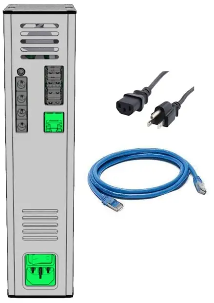
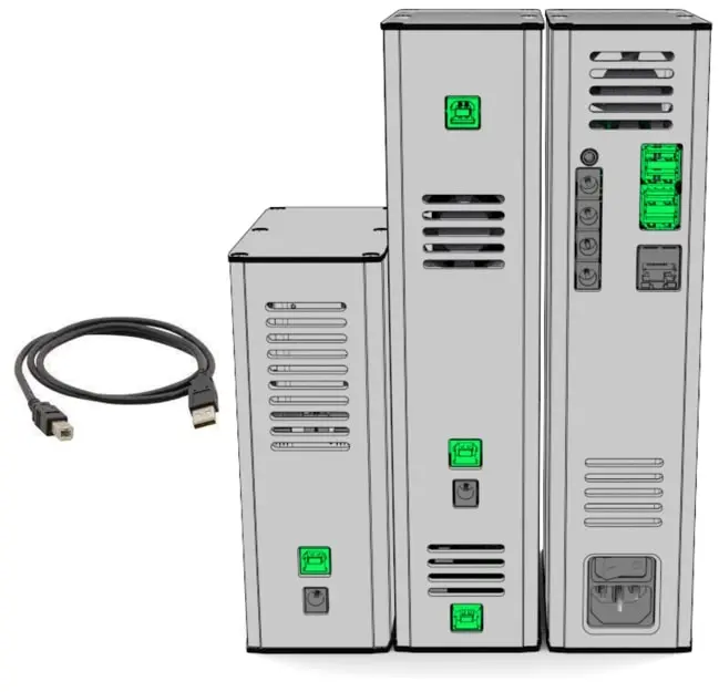
- Plug in the power connector, as well as the CAT5 ethernet cable to the Power Tower, as shown in the image below. DO NOT SWITCH THE POWER ON YET. This will be done at a later time.
- Plug in the included 24 V power cables into outlets in the Power Tower (right) on one end and the power inputs for the Mini Analyzer’s pump and stand-alone pump (middle and left) as shown in Green in the picture below:
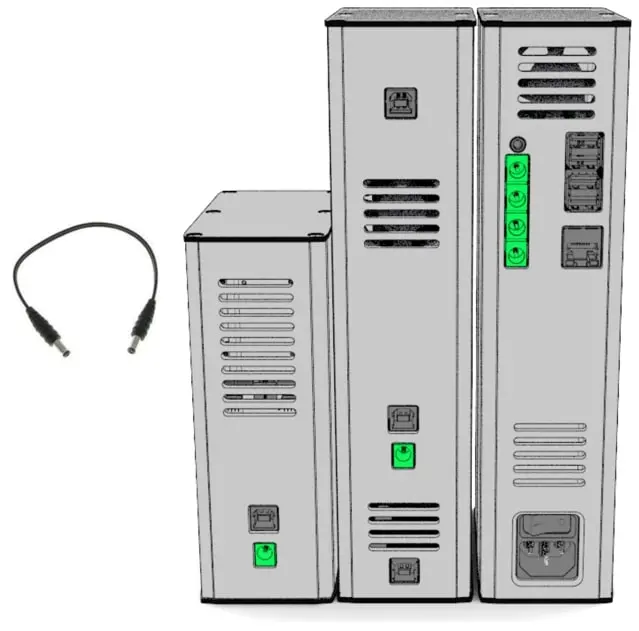
- Now, take each of the 4 included USB cables and plug the A-side into each Power Tower’s ports, as shown in Green below (right).
- Then, plug in the B-side of each cable into each of the 4 component’s ports (middle and left).
Setting up your Alltesta™ Mini Analyzer
- Now let’s connect the capillary tubings.
Three types of tubing - yellow, green, and clear - should be used. The yellow and green tubing is made of a special plastic, PEEK, and they are used for the high-pressure connections of the system. Clear tubing, made of Teflon, is used for low-pressure liquid connections (such as from your mobile phase to the pump inlet or from the detector output to your waste beaker). Before you start, make sure that when you insert the tubing into the fittings that they stick out about 3 mm like in the picture below.
Please note: the fittings need to be inserted along with the capillaries. You cannot insert the fittings beforehand. While you are inserting fittings, gently push the capillary toward the port to ensure the end of the capillary extends beyond the fitting’s tip after it is installed. Tighten the fitting with maximum force using your fingers, and do not use any tools to tighten.

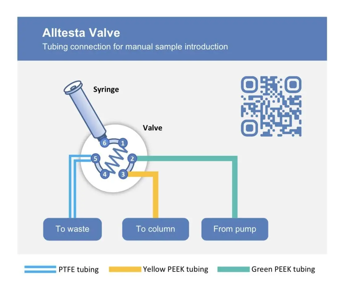
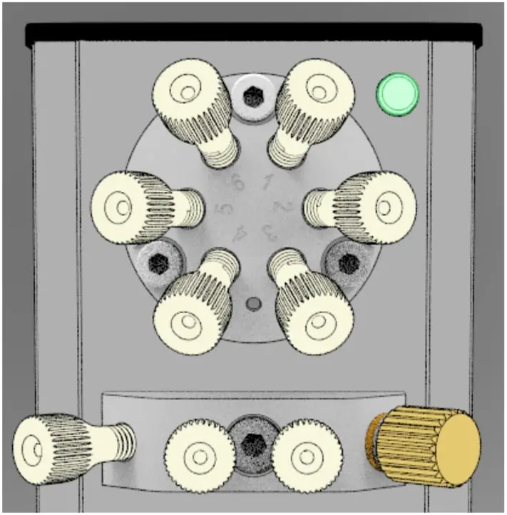
- Connect a short green capillary from position 1 of the valve outlet to position 4.
- Connect a green capillary from position 2 to the right port of the Mini Alzyer pump as shown below (not the gold purge port; the second pump will be connected here).
- Remove the black plugs on each end of your column.
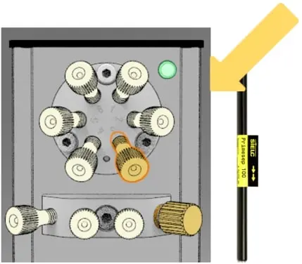
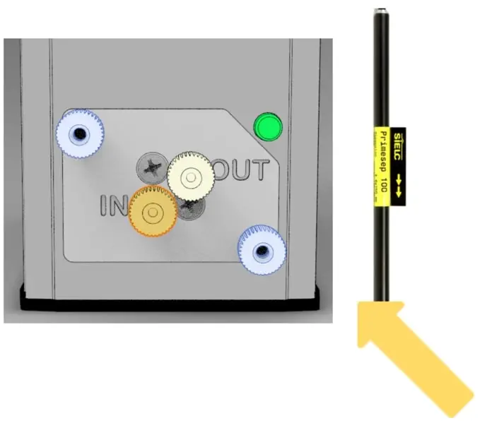
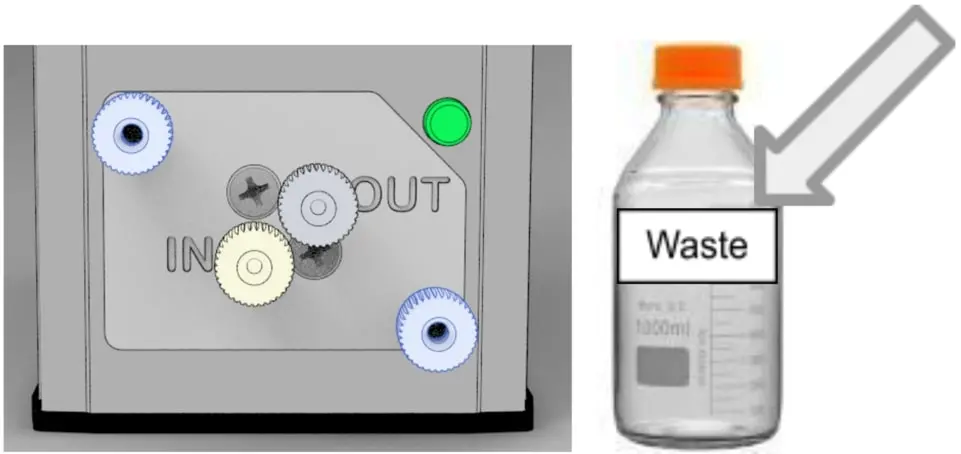
Connect a yellow capillary from position 3 to the inlet of the column. Then use another yellow capillary to connect the outlet of the column to the IN position of the detector.
Note: the arrows on the column label indicate the flow direction of the column. Attaching it correctly will ensure proper column operation. Attaching it incorrectly can harm the column’s performance and lifetime.Note: the arrows on the column label indicate the flow direction of the column. Attaching it correctly will ensure proper column operation. Attaching it incorrectly can harm the column’s performance and lifetime.
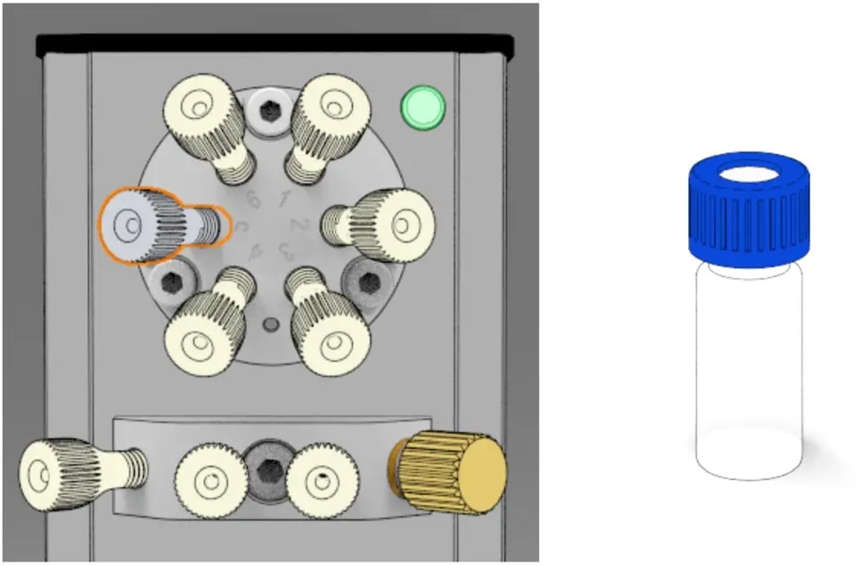
- Connect a clear capillary from position 5 to a sample vial.
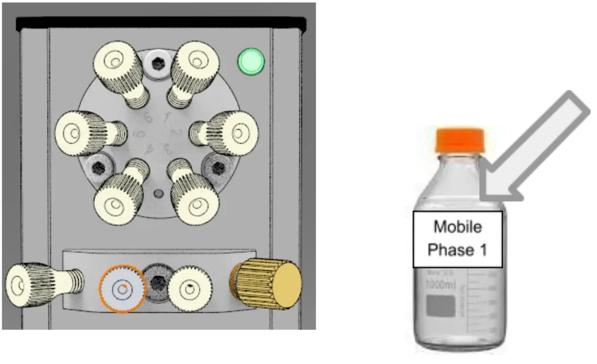
- Connect another clear capillary from the middle-left position on the pump to a beaker with the first bottle of mobile phase (MP1).
- Connect a clear capillary from the OUT position on the detector to the waste beaker.
- There is an additional liquid port on the far-left end of the pumps. This connection is used to wash the pump’s back seal with solvent to protect it from the build-up of salt when a buffer with high salt content is used. In most cases, this port does not need to be connected and can be left open.
On the far-right side of the pump there is a connection called the purge port. This port has a few uses; generally, it is used to quickly replace the content of the pump with a new mobile phase or to get rid of air if the pump was (accidentally) used dry. With the gradient system, the purge port on the Mini Analyzer pump will be where the stand-alone pump connects to the rest of the system. On the far-right side of the pump there is a connection called the purge port. This port has a few uses; generally, it is used to quickly replace the content of the pump with a new mobile phase or to get rid of air if the pump was (accidentally) used dry. With the gradient system, the purge port on the Mini Analyzer pump will be where the stand-alone pump connects to the rest of the system.
Usually, there is a PEEK plug that is screwed into the port (this will be the case of the stand-alone pump). To replace the mobile phase or to remove air, unscrew the plug and screw in a fitting with a capillary connected to a waste flask. Turn the pump ON (via the HPLC.cloud application). Doing this will bypass the column and quickly flush out the solvent. Alternatively, a new mobile phase can be pushed through the column with a normal flow rate.
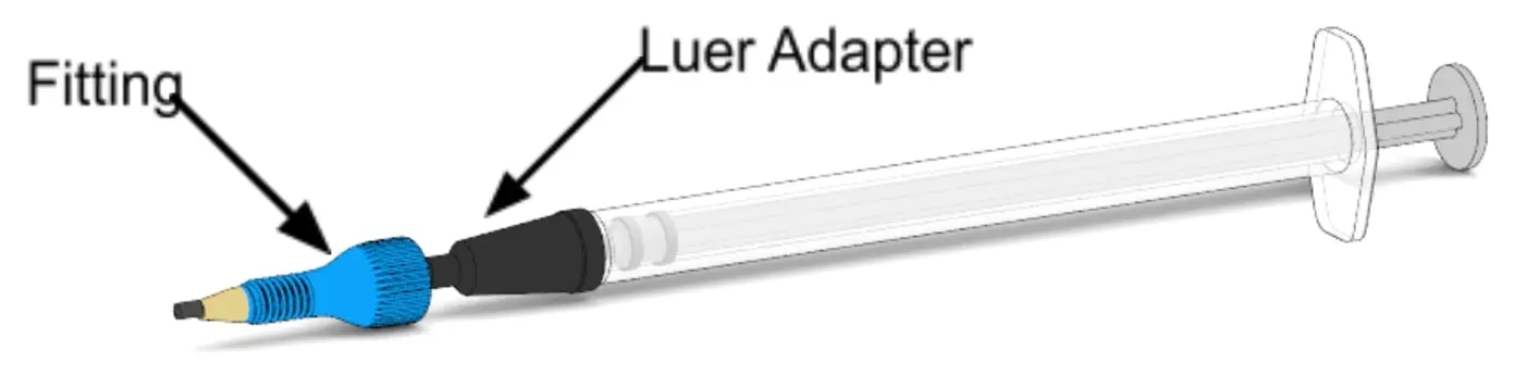
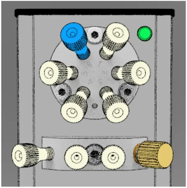
- Place a luer adapter on one of the included 1 mL syringes, collect your sample, and place a fitting over the adapter.
- Screw this fitting into position 6 of the valve, shown in blue.
- Connect another clear capillary from the middle-left position on the stand-alone pump to a bottle with the second mobile phase (MP2).
- Unscrew the plug in the Purge Port on the Mini Analyzer Pump. Connect a green capillary from the middle-right port of the stand-alone pump to the open Purge Port on the Mini Analyzer Pump, as shown below. Keep the plug in the purge port of the stand-alone pump.
- Check over all the fittings by turning them firmly to the right to make sure everything is liquid-tight and secured to ensure no leakage. If any connection exhibits a small leak once you start the pump, it can be tightened by an additional clockwise turn (fingers only).
- Lightly pull on all the capillaries (and syringe adapter) that are inserted into the fittings and columns. If it holds in place, that means it is secure; if you can wiggle it or even pull it out then the capillary needs to be re-inserted with the fitting to become secure.
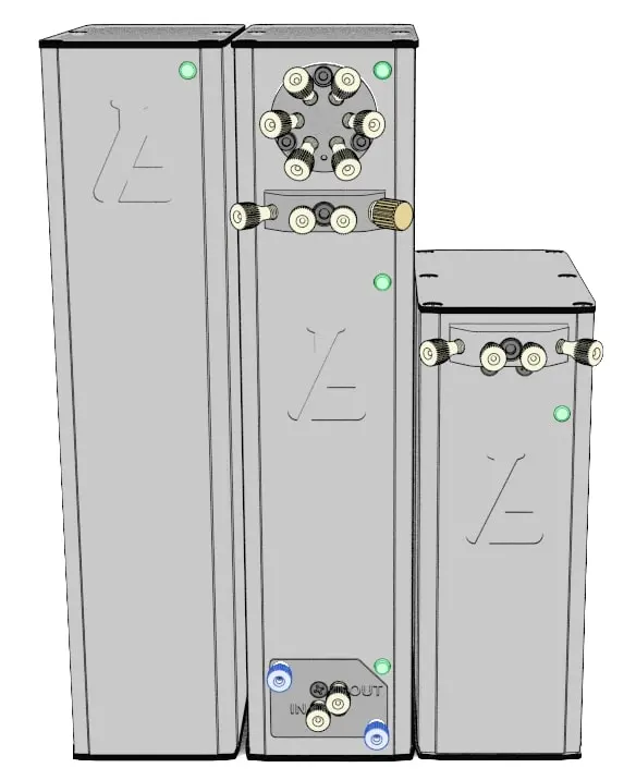
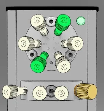
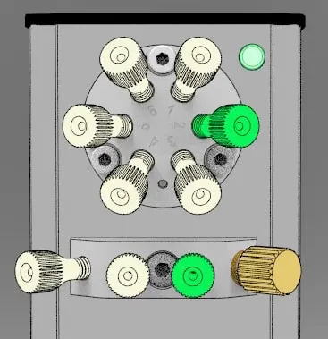
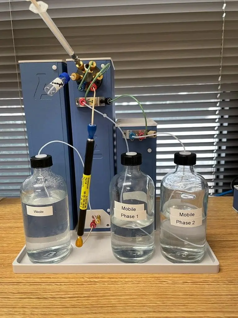
- If you have assembled everything correctly, your system should look like the photos below:
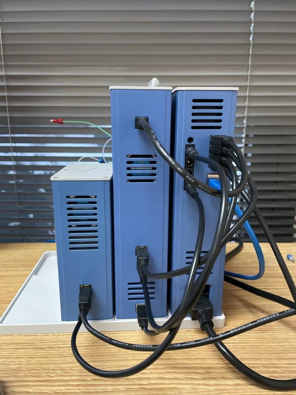
- Now that you have all the liquid and electrical connections installed, it is time to switch the power to ON. The switch is located on the bottom of the back-side of the Power Tower.

- Please allow for the tower to boot up and come online as it needs to install the software. This may take a few minutes. Wait until the front indicator light turns yellow.

- If the unit can communicate with the cloud server, the light on the front of the Power Tower will turn green. This may take a few minutes. When it turns green, the instrument is ready to be used and the cloud software should be up and running.

- For reference, there are a total of 5 colors that can appear on the instruments:
- Green slow blinking light: System is Ready;
- Yellow slow blinking light: Booting up software, instrument is getting ready;
- Magenta: Instrument is working;
- Cyan Short Blink: Software updating;
- Red Short Blink: Hardware/Software Error.
- The lights also serve as physical buttons with different functions depending on the device:
- Pump: hold for 1 sec to recalibrate pressure sensor to 0 psi;
- UV VIS Detector: hold for 1 sec to calibrate LEDs;
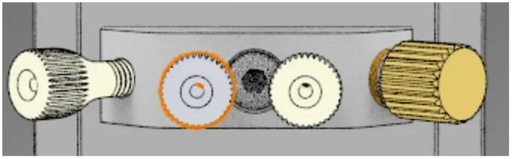
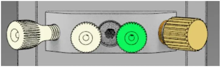
- Valve: hold for 1 sec to switch positions;
- Holding down the button for about 10 sec on any unit will reboot that particular unit.
- When the system is properly installed and the light on the Power Tower and each unit is green, the cloud software should be open and ready to set up. Follow the HPLC Cloud Software Set-up Manual to get your system connected and begin testing!
Example Injections
- Ensure your system is set up as shown in the pictures in steps 26 and 27, but with the following modifications:
- You will only need 1 pump (the pump housed in the Mini Analyzer) for this experiment, so you can remove the connection to the stand-alone pump and plug the purge port.
- Connect the included Newcrom R1 column (front) to Position 3 on the valve stator and (end) to the Inlet of the detector.
- Ensure that the arrows on the column are pointing down toward the direction of the detector.
- Connect the included MeCN/H2O/TEAP - 10/90/40mM Mobile Phase to Pump Inlet.
- Place the included vial of Caffeine on the clear tubing protruding from Position 5.
- Slowly pull the plunger of the syringe so that liquid starts to enter the loop and syringe.
- Once you start to see liquid appear in the syringe, stop pulling the plunger.
- In HPLC.cloud, set your method settings to the following:
| Run Time | Mobile Phase | Buffer | Flow Rate | Pressure min | Pressure reach time | Sample Amount | Injection time | Injection Delay |
|---|---|---|---|---|---|---|---|---|
| 5 min | MeCN/H2O - 80/20 | TEAP - 40 mM | 1.0 | 200 | 20 | 1 | 10 | 0 |
- Click “Save.”
- Start your Injection in HPLC.cloud by clicking “Quick Start”.
- The system will now automate the rest of the injection. You can follow what the detector sees in real time by clicking on the name of the injection in the box that appears at the top of the screen.
- You should see a peak around 4 minutes.

Example Injections
- Fill three 1.5 mL vials with distilled water and label them #1-3.
- Replace the sample vial with Wash Vial #1 on position 5.
- Insert the clear tubing from position 5 into Wash Vial #1.
- Raise the plunger to the max position in the syringe to pull the water through the valve and loop.
- Depress the plunger to the minimum position in the syringe to push the water back into the vial.
- Replace Wash Vial #1 with Wash Vial #2 on position 5.
- Repeat Steps 3 and 4.
- Replace Wash Vial #2 with Wash Vial #3 on position 5.
- Repeat Steps 3 and 4.
- Replace Wash Vial #3 with the Waste beaker and remove any remaining water in the valve and loop.
- Remove the Waste beaker and replace it with your next sample.
- This can all be done during sample runs, but only after the injection itself (after the valve exits Injection Mode.
- You can reuse the same wash vials for a few experiments, but make sure to replace the water occasionally in order to minimize the presence of unwanted compounds.